Solar harvesting into Lithium Ion Capacitor
Sold by JasperSikken · in Solar
★★★★★ 5 / 5 · (1 verified review)A highly efficient solar powered Li-ion charger with two regulated outputs


I designed this board because of a recent price drop in Lithium Ion Capacitors (LICs) and I believe LICs combine many advantages of Li-ion batteries and supercapacitors making it a perfect choice for batteryless IoT applications.
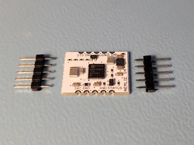
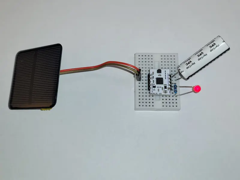
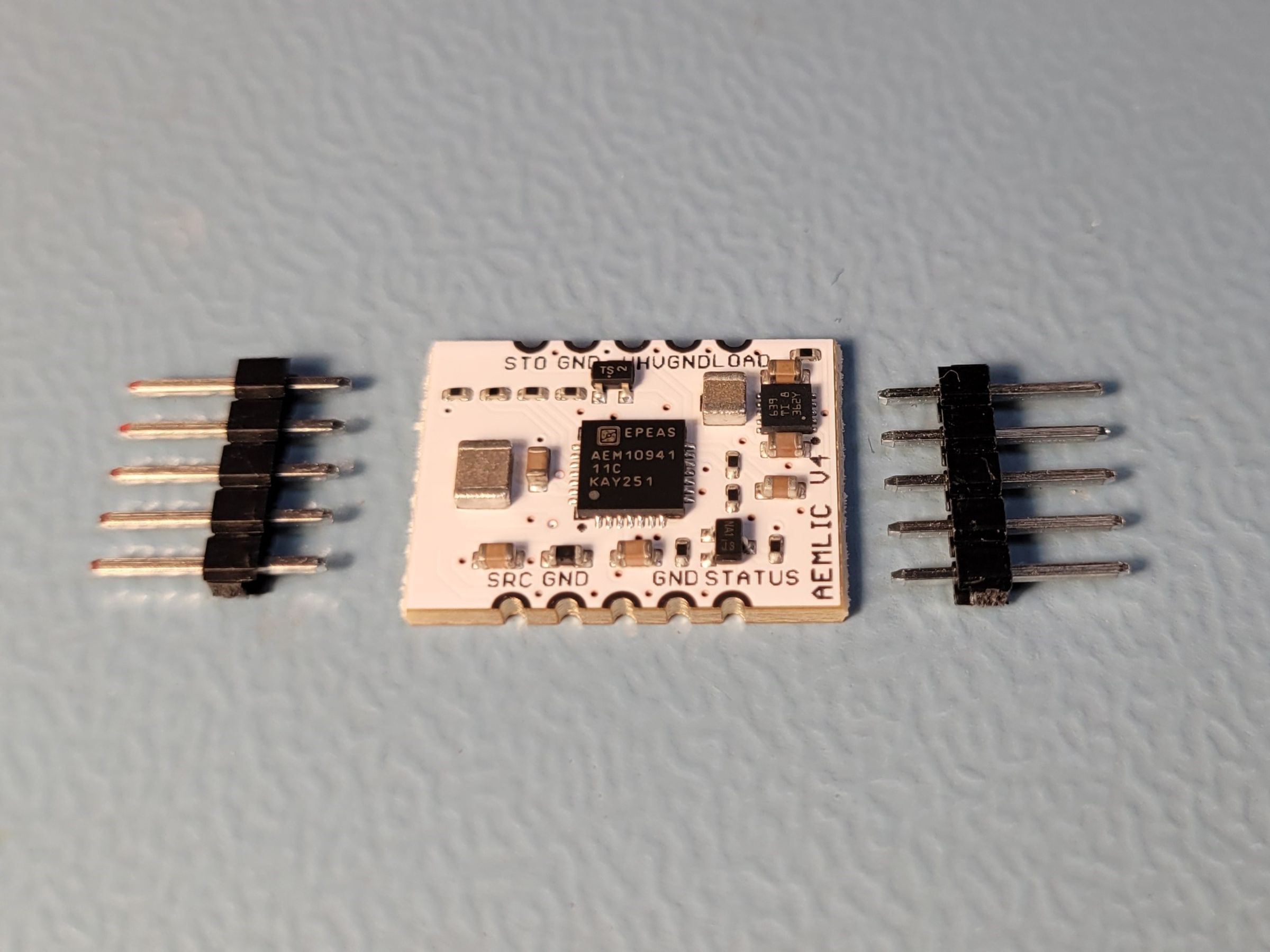
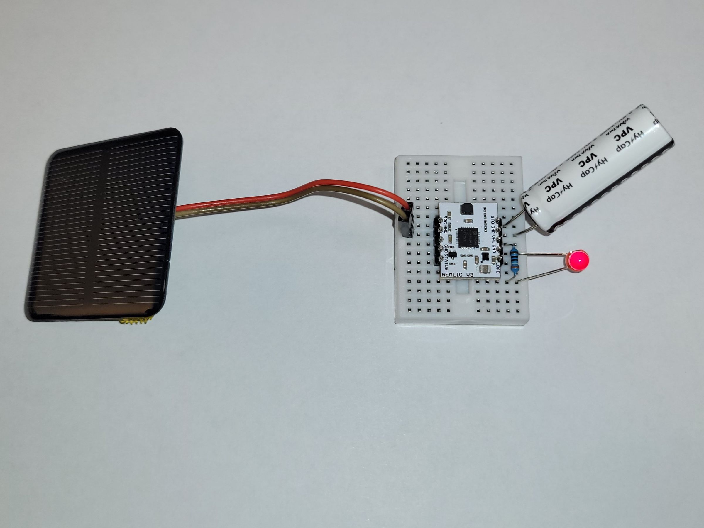
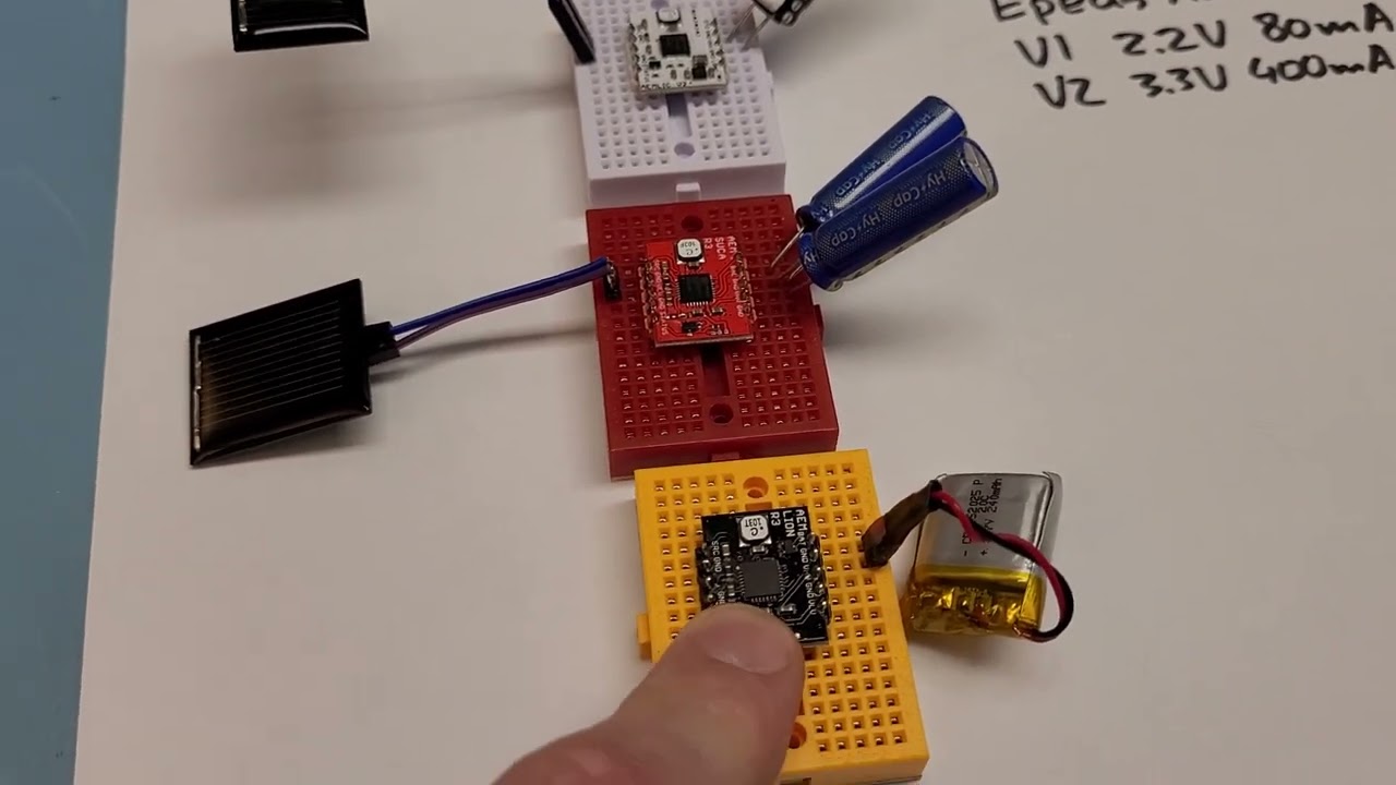
The AEMLIC is a 15x20mm board with the AEM10941 Solar Harvesting IC from E-peas. It efficiently converts solar panel energy into **LIC **charge, it even works with indoor light. It has a regulated output that is enabled when the LIC has sufficient charge, and a low voltage warning that informs the user of impending shutdown when the LIC runs low. It easily integrates in other projects because of the castellated via's, and when soldered onto 0.1' pitch headers it fits in a bread board.
This board is ideal for solar powered IoT devices because it integrates maximum power tracking, LIC charging, and it has a regulated voltage output in a tiny and easy to integrate board.
Ideal for indoor applications
The AEM10941 harvesting IC is very suitable for indoor applications because it has an ultra low power startup. The boost converter starts at a very low 380 mV input voltage and 3 uW input power. The IC gets most power out of the solar cells by doing MPPT maximum power point tracking every 5 seconds.
Specifications
- PCB 15*20mm
- solar input voltage 50mV to 5V
- ultra low power startup 380mV/3uW
- solar input current max 125mA
- MPPT every 5 secs, MPPT set to 70%
- Storage element: Lithium Ion Capacitor (LIC) you need to add yourself
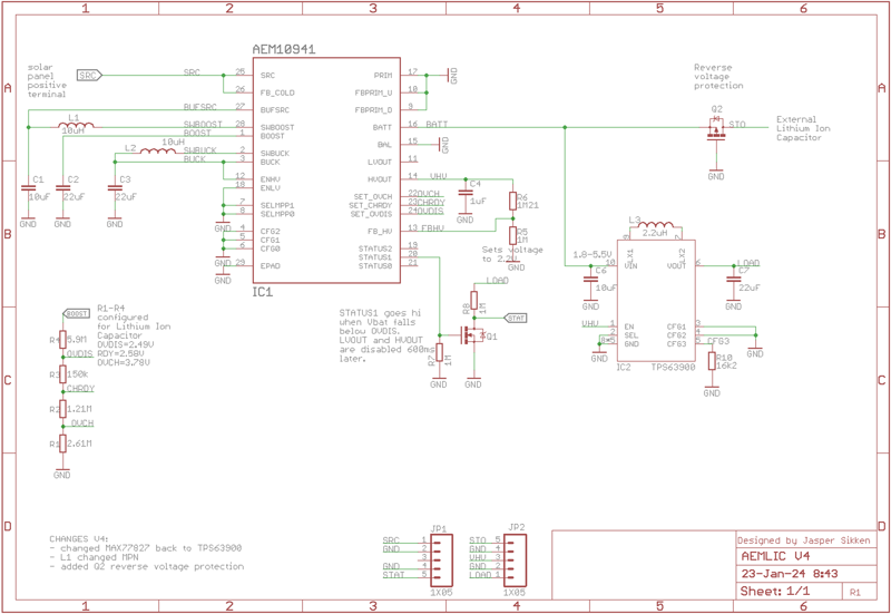
- Two outputs: 2.2V/80mA and a 3.3V/500mA output (1.5uA quiescent current)
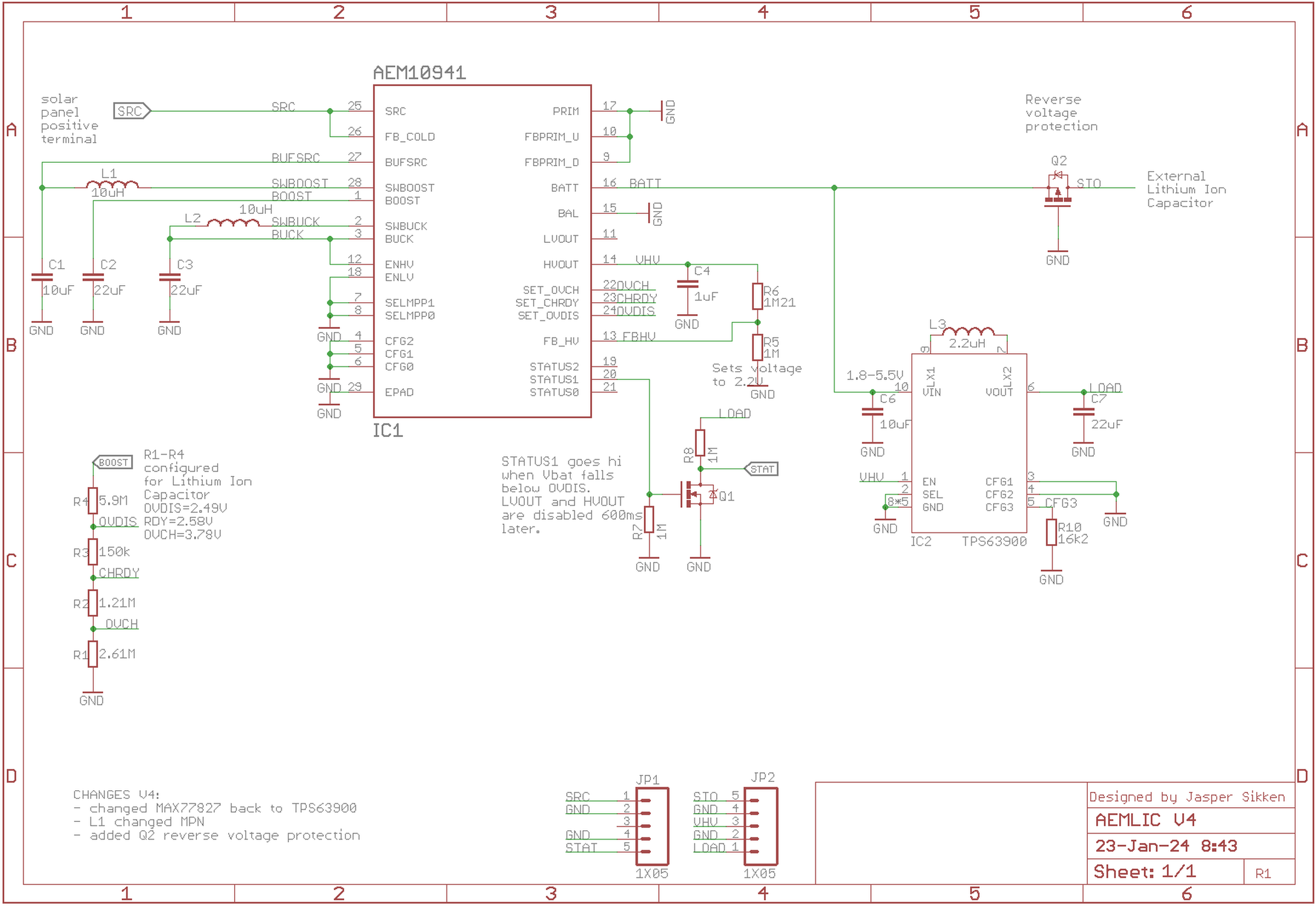
- the regulated outputs are enabled when LIC voltage has exceeded 2.58V (enable threshold) and not fallen below 2.49V (disable threshold). The LIC is charged up to 3.78V.
- the status output pin warns the host MCU if LIC voltage drops below 2.49V and 600ms before shutting down the regulated outputs
What you get
- A soldered and tested AEMLIC
- 2x 5pins 0.1" male headers
Pinout
- SRC - solar panel positive terminal, input to the harvesting IC
- GND - ground
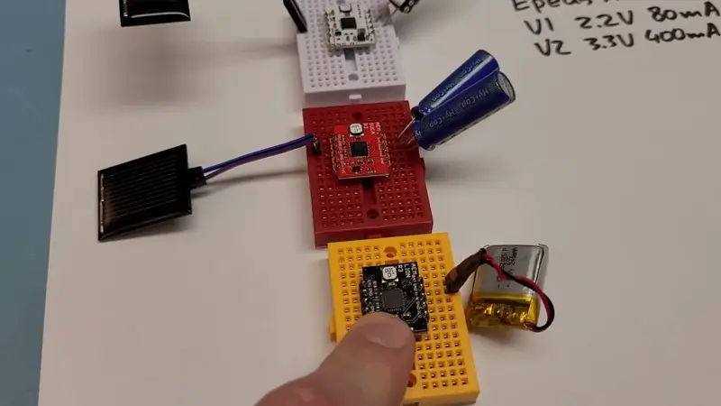
- STAT - status output pin, open drain output with 1M pull up (to 2.2V in V1, and 3.3V in V2/V3), active low. When LIC voltage falls below 2.49V it goes low 600ms before the VHV output is disabled. Can be used to warn the host MCU to gracefully terminate writing to EEPROM/flash and prepare for power outage.
- STO - Connection to positive terminal of the LIC
- VHV - 2.2V/80mA regulated output
- LOAD - 3.3V/500mA regulated output
Warning
The solar harvesting chip max input voltage is 5V. Please be aware that a 5V nominal solar panel can be 6.5V when unloaded. Alway check the solar panel open circuit voltage, or Voc.
What is the expected charge current?
I have measured charge current using three different solar panels in indoor light (500 lux), outdoors in the shadow, and in full sun (~500W/m^2 which is not very powerful for full sunlight).
| Solar panel | indoor 500 lux | outdoor shadow | outdoor full sun 500W/m^2 |
| ---------------- | -------------- |-------- | ----- |
| 1V/80mA 30x25mm | 50uA | 700uA | 5mA |
| 2V/100mA 79x28mm | 100uA | 1.8mA | 10mA |
| 4V/100mA 70x70mm | 280uA | 4.8mA | 20mA |
Indoors (~500 lux) and with the smallest solar cell the storage element is charged at 50uA for 10 hours. Then the application must have an average current of (50uA*10hrs/24hrs) 20uA or less. That's enough for a simple Bluetooth Low Energy beacon or a very simple LoRa application. If that is not enough you need to select a larger solar panel.
Outdoors, in shadow current is 10-20 times larger. And in sun 100 times larger.
Compatible solar panels
Lithium Ion Capacitors I have used
- Vinatech 3.8V 30F LIC
- Eaton 3.8V 30F LIC
- Vinatech 3.8V 100F LIC
- Vinatech 3.8V 250F LIC
- CDA 3.8V 250F LIC
- CDA 3.8V 750F LIC
- CDA 4.0V 1100F LIC
- CDA 4.0V 350F LIC
How long can an application run on a fully charged Lithium Ion Capacitor?
Rule of thumb: When a 1F capacitor is loaded with 1A the voltage will drop 1V in 1 second. The AEMLIC charges the capacitor up to 3.78V and the output is enabled down to 2.49V. If your application draws 30mA from the 3.3V output, then it will run for: 250F*(3.78V-2.49V)*90%/0.03A= 10750s = 2.7 hrs
Can I put two Lithium Ion Capacitors in parallel?
No problem. When two of the same capacitors are put in parallel the capacitance doubles. LICs have a very low internal leakage. I measured that a 250F LICs only have few uA leakage and that is about 5 times lower than supercapacitors.
How to solder the pin headers?
Use an old bread board, stick the pin headers in and place the PCB on top, then start soldering.
How does LIC compare to other storage devices?
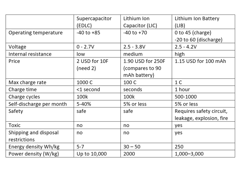
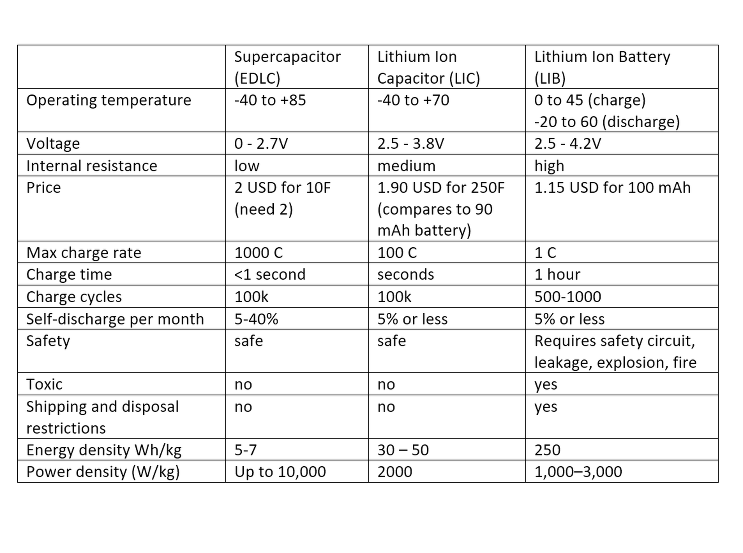
Compared to Li-ion batteries LICs are non-toxic, don't need protection circuits, they don't have shipping restrictions and can be disposed with normal electronics. Compared to supercapacitors LICs have much higher energy density and a much lower leakage. Please see one of the images to see a comparison table with Li-ion battery and supercapacitor. A 250F has the same capacity as a 90 mAh Lition Ion battery.
Can I change the charge voltage?
I don't recommend it, because it requires very good soldering skills to change a few 0402 resistors. Check out this hackaday.io log.
Solar harvesting into Lithium Ion Capacitor - In the news!
March 30 2022 - Hackaday wrote blog post about V2
Jan 2022 - Andreas Spiess discussed V1 in a video
May 4 2021 - Tindie wrote blog post about V1