
Voltage divider from 12v to 3.3v for esp or arduino gpio high impendance
Sold by Labo Innopy
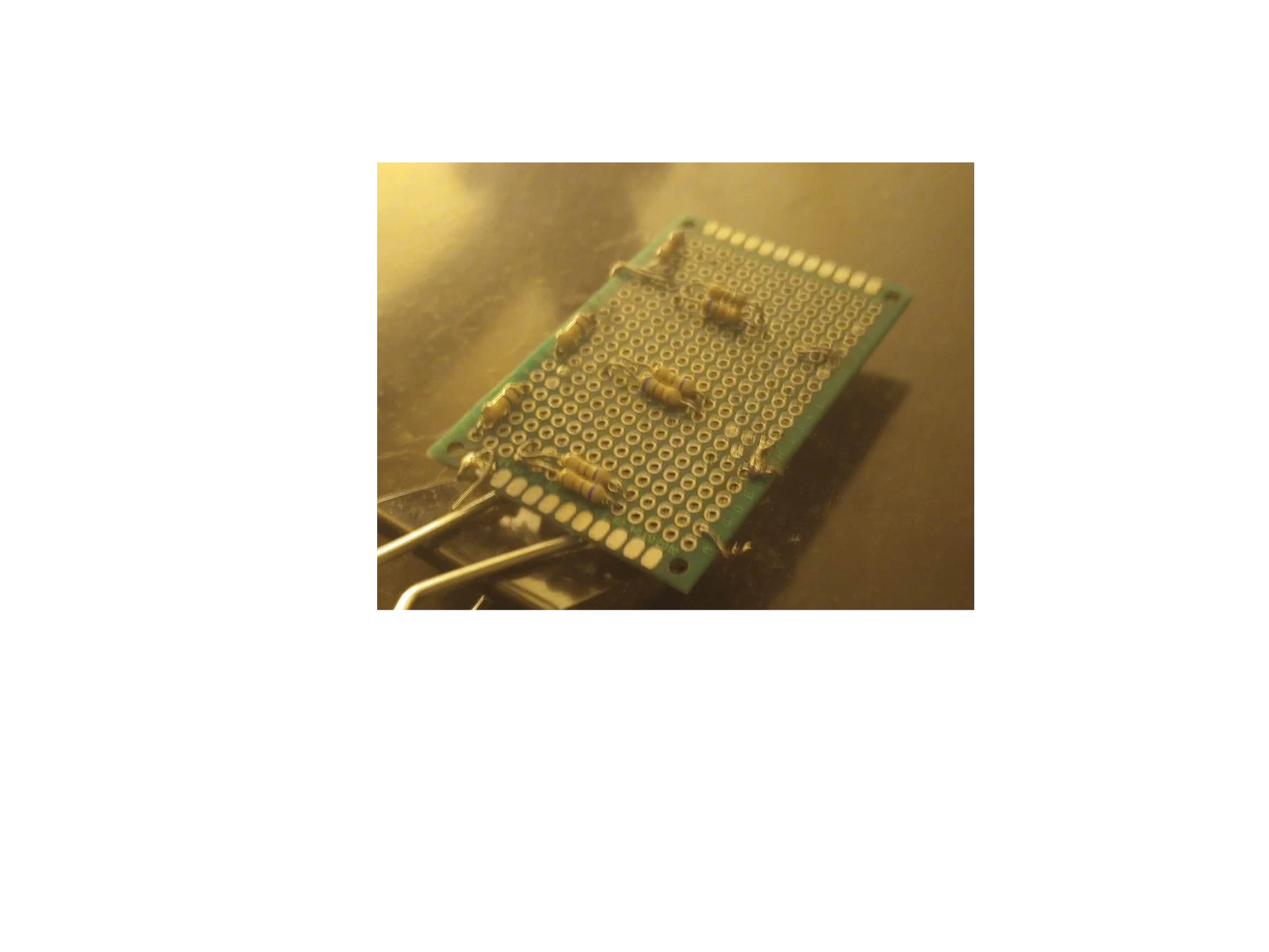
This module is a miniature, multi-port step-down regulator designed to convert a single 12V DC input into three independent 3.3V output rails. Engineered for low-draw, small-run electronics projects, it features three distinct output ports, making it a clean way to power multiple 3.3V peripherals simultaneously without messy daisy-chaining
This 3-channel voltage divider module is designed to safely scale 12V signals—such as light switch statuses or battery voltages—down to 3.3V levels compatible with ESP32 or ESP8266 microcontrollers.
This passive circuit is optimized strictly for logic detection and analog voltage measurement with minimal current draw.
Module Description
This compact signal conditioning board features three independent channels of resistive voltage division. It provides a secure interface between high-voltage peripherals (like 12V automotive, home automation, or industrial light switches) and the sensitive GPIO pins of an ESP microchip, preventing overvoltage destruction.
Technical Specifications
- Maximum Input Voltage: Nominal 12V to 15V DC (on input ports).
- Safe Output Voltage: ≤ 3.3V DC (perfectly tailored for ESP32 GPIOs).
- Channel Count: 3 independent input ports / 3 corresponding output ports.
- Circuit Topology: Passive, high-precision voltage divider network (1% tolerance resistors).
Application Examples
- Light Switch Interfacing: Detects the ON/OFF state of a 12V light switch. When the switch closes, the module steps the 12V signal down to 3.3V to register a
HIGHlogic level on the ESP32 pin. - Battery Voltage Measuring: Allows the ESP32 to safely read and monitor a 12V battery system through its Analog-to-Digital Converter (ADC) by bringing the voltage into the standard 0–3.3V range.
1. Resistor Selection
To scale 12V down to exactly 3.3V, the ratio between resistor R₁ (input side) and resistor R₂ (ground side) must be:
\(\frac{V_{\text{out}}}{V_{\text{in}}}=\frac{3.3}{12}=0.275\)
Using standard, readily available resistor values to keep current draw around 1mA:
- R₁ = 8.2 kΩ
- R₂ = 3.12 kΩ (or a standard 3.3 kΩ resistor, which yields a safe 3.44V if the maximum input is capped, though a slightly larger R₁ like 10 kΩ with a 3.3 kΩ R₂ restricts the output to 2.98V—safely registering as a logic
HIGHwhile protecting against 14V automotive spikes).
2. Single-Channel Wiring Diagram
12V Input (Switch/Battery) ---> [ R1 (10k) ] ---> Output Point (3.3V Max to ESP32 Pin)
                                                      |
                                                [ R2 (3.3k) ]
                                                      |
Common Ground (GND) <---------------------------------+-------------------------------
✅ Summary
This 3-port divider module provides an efficient, hardware-safe link for your ESP32 to detect 12V light switch positions or sample 12V power levels without complex active components.
Let me know if you would like to proceed with:
- The exact resistor values based on your maximum possible voltage (e.g., 12V flat vs. 14.4V alternator voltage).
- A sample Arduino/ESP32 code snippet to read the switch state or measure the voltage accurately.