Solar linear lithium ion capacitor charger board
Sold by JasperSikken
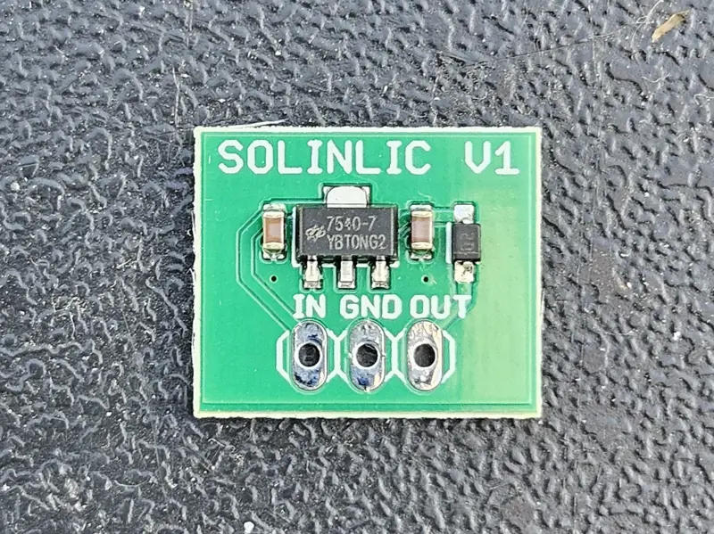
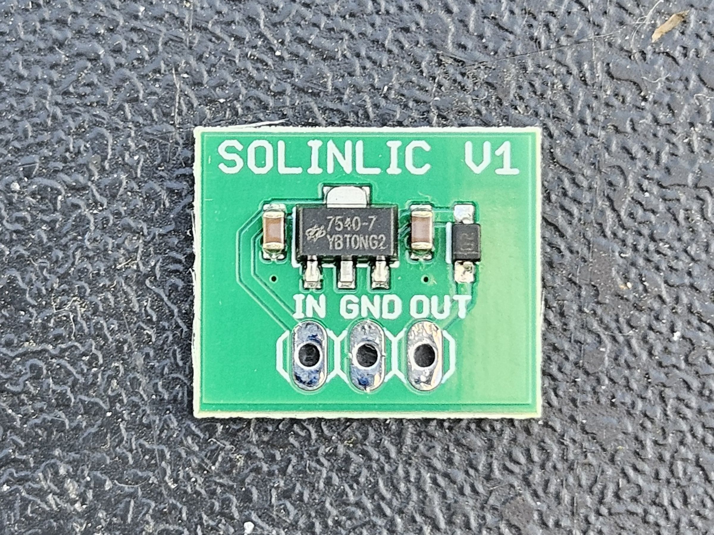
This board efficiently charges a 3.8V lithium ion capacitor using a linear regulator


What is it?
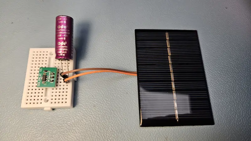
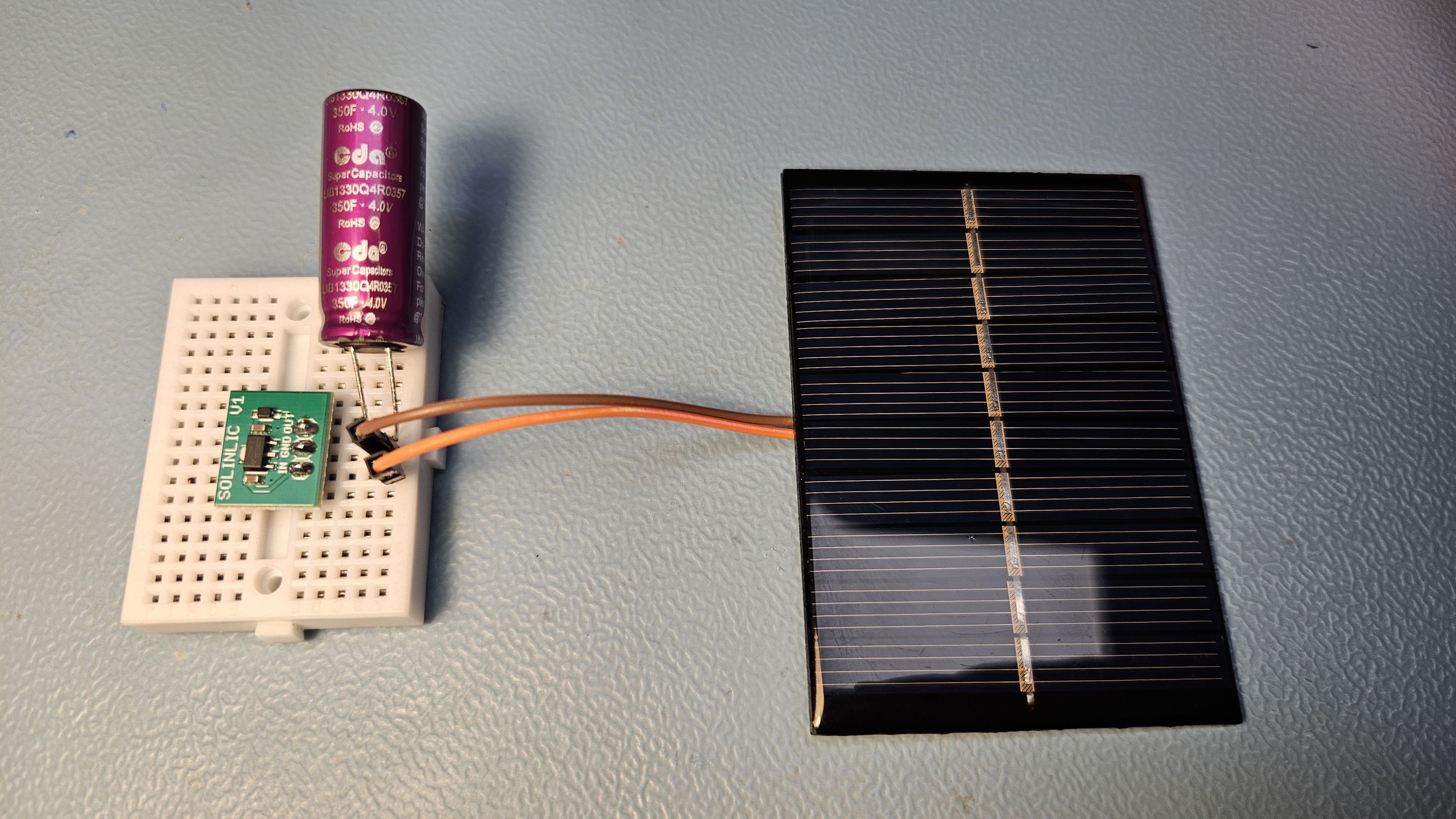
When combined with a 5.0V solar panel this board efficiently charges a 3.8V Lithium Ion Capacitor, it even charges from indoor light, 400 lux. Due to the low voltage drop of the LDO (0.04V) and the reverse current blocking diode (0.3V) this is more than 90% efficient and the solar panel works near to maximum power voltage. This board uses a 4.0V low quiescent current LDO and a low reverse current Schottky diode to charge the capacitor to maximum 3.8V. It was tested at both indoor light level 400 lux as well as outdoors on a cloudy day 2500-5000 lux and compared to a highly efficient switching energy harvesting chip. Outdoors it slightly outperformed the switching chip making this a very efficient and cost-effective alternative to expensive switching ICs for applications that sometimes see outdoor light.
Specifications
- input voltage max 30V (5V solar panel recommended)
- output voltage 3.8V max
- output current 100mA specified, measured >350mA
- thermal protection 160 degrees C
- quiescent current max 4uA
- use with 3.8V or higher voltage lithium ion capacitor
- use with a 5V solar panel like this one 5V 120mA
What you get
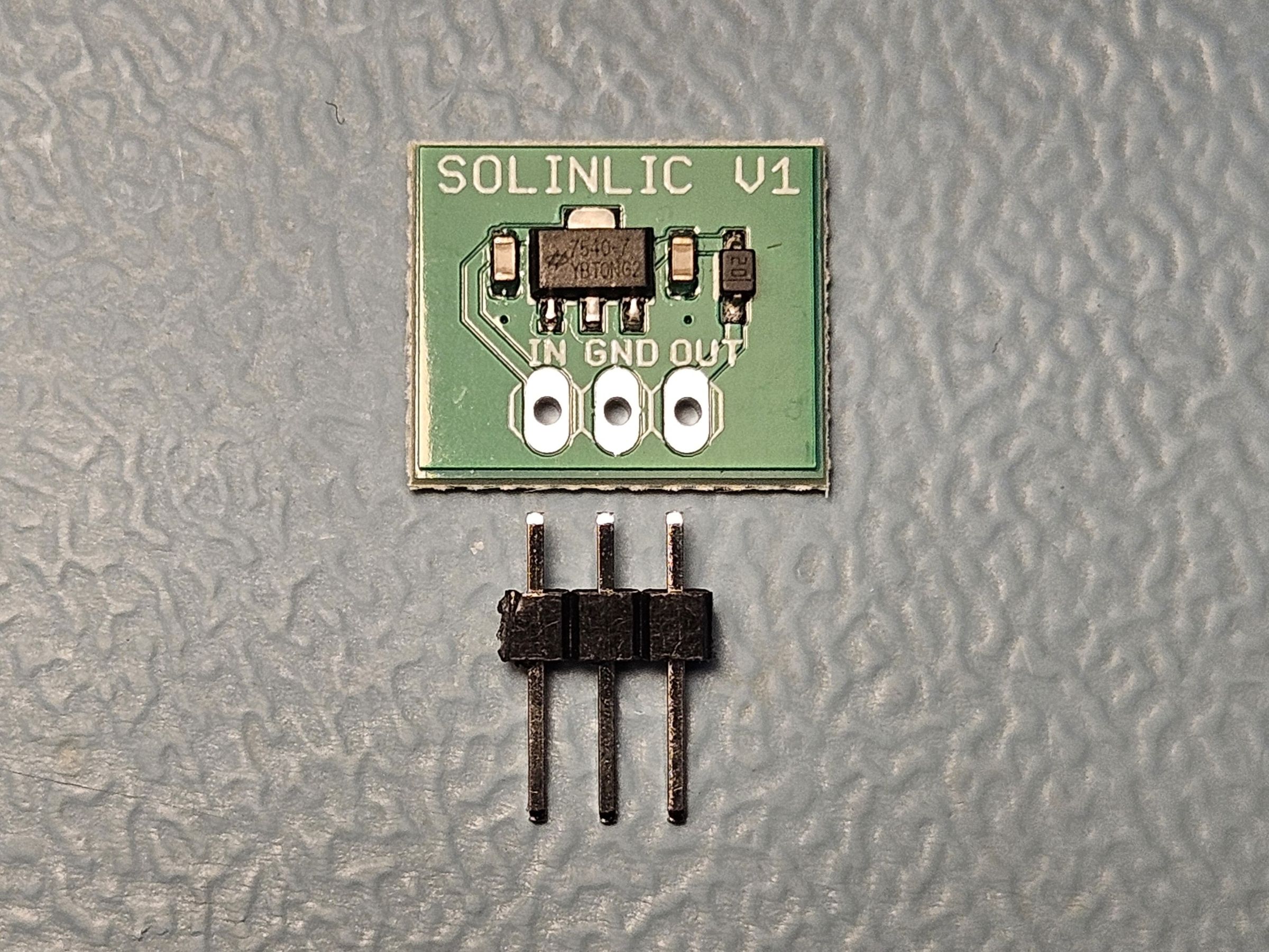
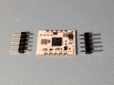
- A soldered and tested board
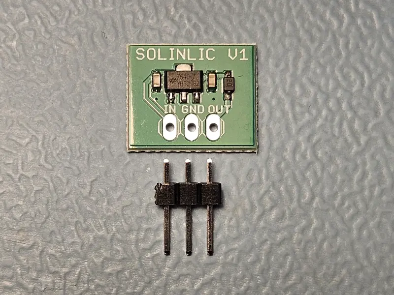
- 3pins 0.1" male header
Pinout
- IN - connect to solar panel positive terminal, max 30V
- GND - solar panel and LIC ground
- OUT - connect to LIC positive terminal, max 3.8V
Tested with
- this 5V 120mA solar panel but it works with other solar panels too
- this 250F 3.8V lithium ion capacitor but it works with other LICs too
- this 1100F 4.0V lithium ion capacitor but it charges only to 3.8V
- this 1300F 4.2V lithium ion capacitor but it charges only to 3.8V
Why did you make it?
I made it because I found that linear charging circuits are very efficient due to their low voltage drop. In addition, the 3.8 V storage unit voltage keeps the solar panel operating near its maximum power point voltage. I was inspired by the fact that, for outdoor applications, it is not necessary to use an expensive switching energy-harvesting chip with maximum power point control. I designed this board because of the ever-increasing development of LIC capacities exceeding 1000 Farads and voltages exceeding 4.0 V. I believe LICs combine many of the advantages of Li-ion batteries and supercapacitors, making them a perfect choice for batteryless IoT applications.
How long can an application run on a fully charged Lithium Ion Capacitor?
Rule of thumb: When a 1 F capacitor is loaded with 1 A, its voltage will drop by 1 V in 1 second. The board charges the capacitor up to 3.8 V, and it can be discharged down to 2.5 V. If your application draws 30 mA from the output, it will run for: 250F(3.8V-2.5V)/0.03A= 10833s = 3 hrs
Can I put two Lithium Ion Capacitors in parallel?
No problem. When two identical capacitors are connected in parallel, the capacitance doubles. LICs have very low internal leakage. I measured that a 250 F LIC has a leakage current of only a few µA, which is about five times lower than that of a supercapacitor.
How to solder the pin headers?
Use an old bread board, stick the pin headers in and place the PCB on top, then start soldering.
How does LIC compare to other storage devices?
Compared to Li-ion batteries, LICs are non-toxic, do not require protection circuits, have no shipping restrictions, and can be disposed of with normal electronic waste. Compared to supercapacitors, LICs have a much higher energy density and significantly lower leakage current. A 250 F LIC has approximately the same capacity as a 90 mAh lithium-ion battery.
Related Products
Reviews
No reviews yet. Reviews can be left after a verified purchase/delivery.